Tag Archives: Jigs

Hex Stair (Part One)

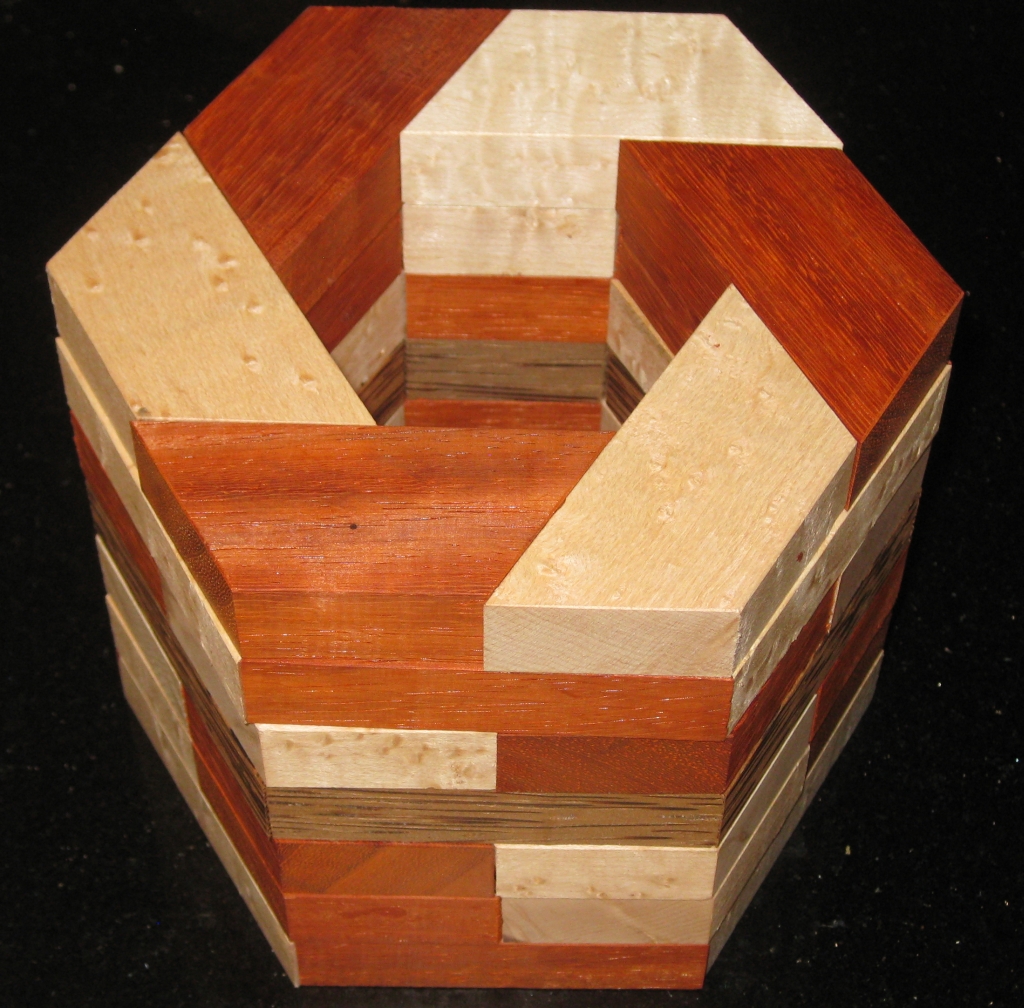
Not too long ago, I posted a few pictures of some of the puzzles I’d been making on Facebook. One of those was a copy of Oskar van Deventer’s design “Oskar’s Domino Tower”. I’ll write about that in another post, however when I did, my good friend Derek Bosch got in touch about a similar design he’d created called Hex Stair. To his knowledge, the design had never been made, and I decided that it would be a fun puzzle to try to build after seeing the design.

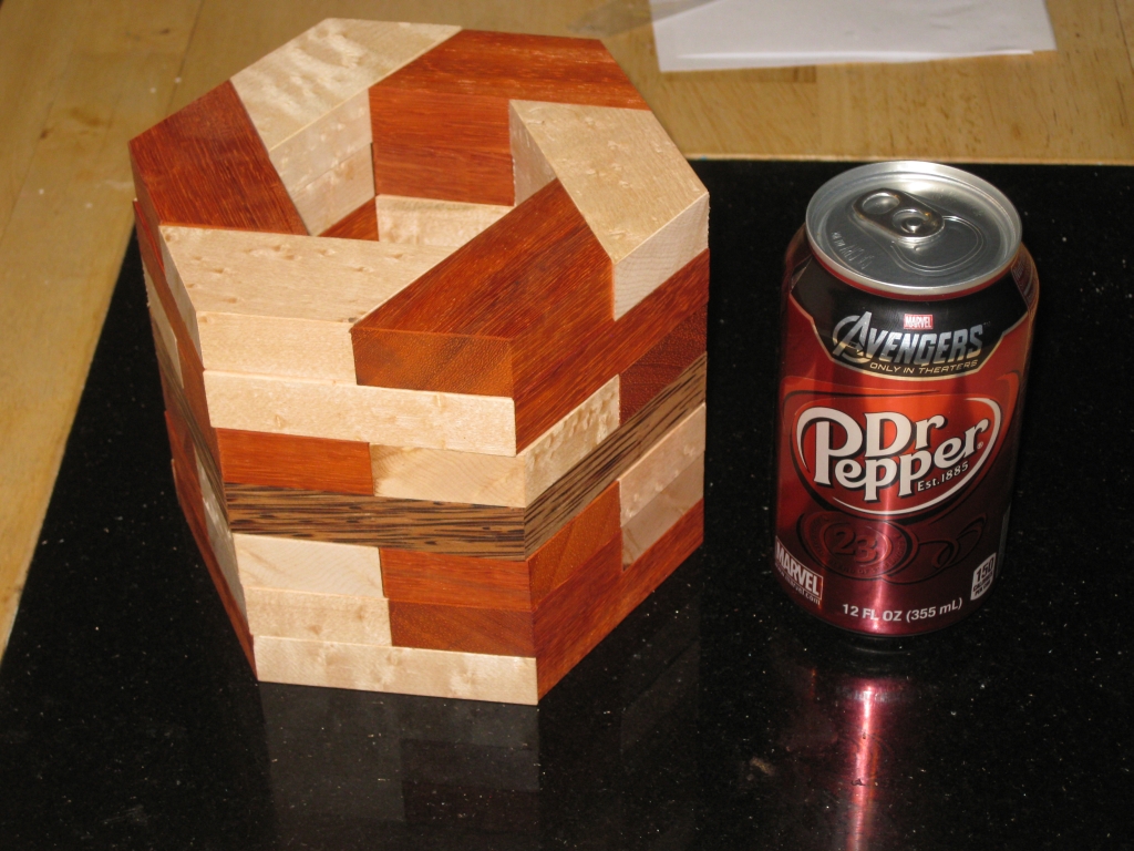
Hex Stair Solved

Hex Stair Solved

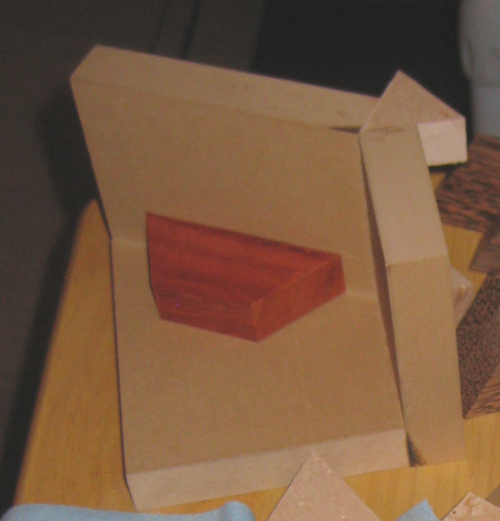
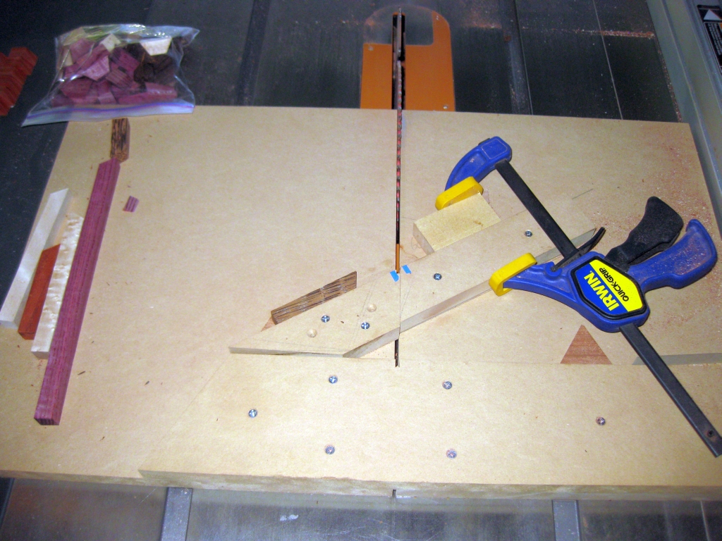
As you can see the design is based on a hexagon. So that means making cuts at a 60 degree angle. To do so repeatedly, I was going to need a new jig, specifically a cross cut sled setup for that angle. I’ve gone through the process to create a cross cut sled before, so I’m not going to go over that again here. I used the same basic MDF construction using 3/4″ boards, and I cut myself some maple runners as guides for the sled. If you want more info about creating the sled, then have a look at my post about going From Square Sticks to Cubes. Clearly rather than a 90 degree angle on the sled I was looking for 60 degrees, and with a little tuning, and a few practice cuts, I had the sled producing perfect angles.

60 degree Crosscut Sled.

60 degree Crosscut Sled.

To do that, there’s no point in measuring just one cut. Rather it’s better to make 6 cuts, creating a hexagon frame, and bring those pieces together. If they come together with no gaps, then you’re golden. If not then you need to adjust the angle of the backstop on the sled. Ed: The reason for doing this is that it multiplies any error in your sled by a factor of 6. I didn’t get things perfect on my first attempt, so I adjusted slightly and then re-cut the test pieces. This time I was pretty close and didn’t think I was going to get much better so I called it good. To make tiny adjustments, a strip of tape can be used to adjust the angle. Obviously I could create a sled with a variable back stop, and have screws to push or pull it for a perfect fit, but for now I’m not looking at spending too much time. If I find many puzzles which require 60 degree angles that I want to make, then I’ll consider making a more advanced jig. Ed: What is it about us that we’re never happy with what we have, we always want it to be better?

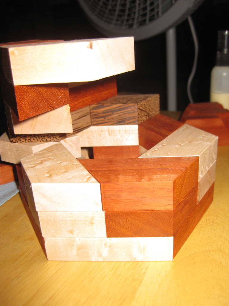
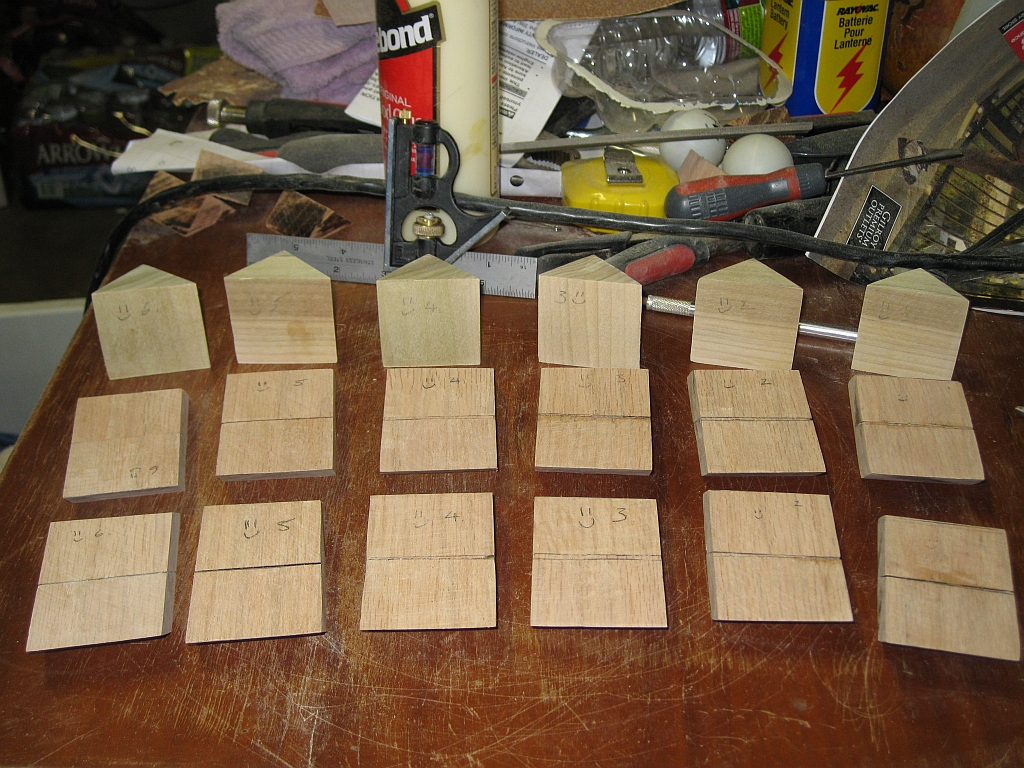
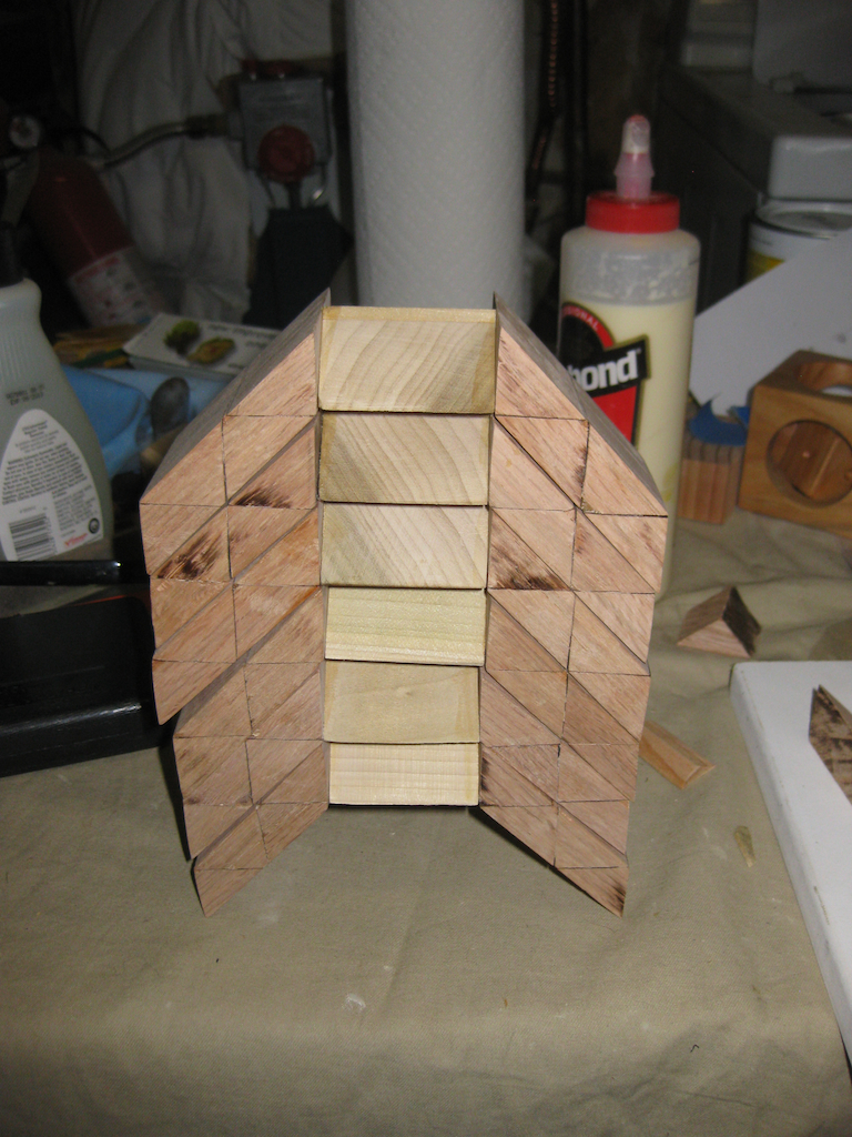
With the sled ready, I milled my stock, selecting some Paduak, Birdseye Maple and Red Palm that I’d had sitting for a while, and got to work on the new jig. There are 42 pieces required to make this puzzle and given that there are 7 layers, I decided to create a band in the centre of the puzzle. Since it’s never been made before, I’m not biased by something someone else has done, and I thought it would look fairly good. You can be the judge, based on the photos! I got to work cutting 18 pieces each of the two main woods, and 6 pieces for the centre ring. With that done, I took the pieces to the router and added a very subtle bevel to the long edges. I quickly found out here that beveling the pointed edges can’t be done on the router as there is nothing for the guide to reference off, and given the thin nature of the pieces, this would be a fairly dangerous cut, so I opted not to bother. I think in the finished puzzle, it works out very well, as it makes it look as though there’s seven rings, rather than 42 individual pieces. Again it’s all personal taste, but I’m happy with the results!

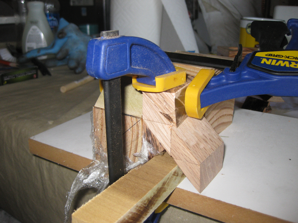
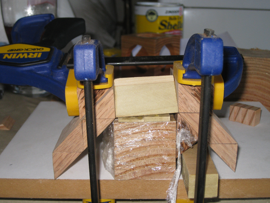
Gluing the pieces together into a finished puzzle presented me with a few interesting challenges. Firstly, it’s not square, so my current gluing jigs are no use. Also the puzzle is fairly tall, with each individual piece of the puzzle having a very small footprint, making it unstable without a lot of support, so ensuring that everything is glued up perfectly alighted is an interesting challenge.

60 degree basic gluing jig

60 degree basic gluing jig

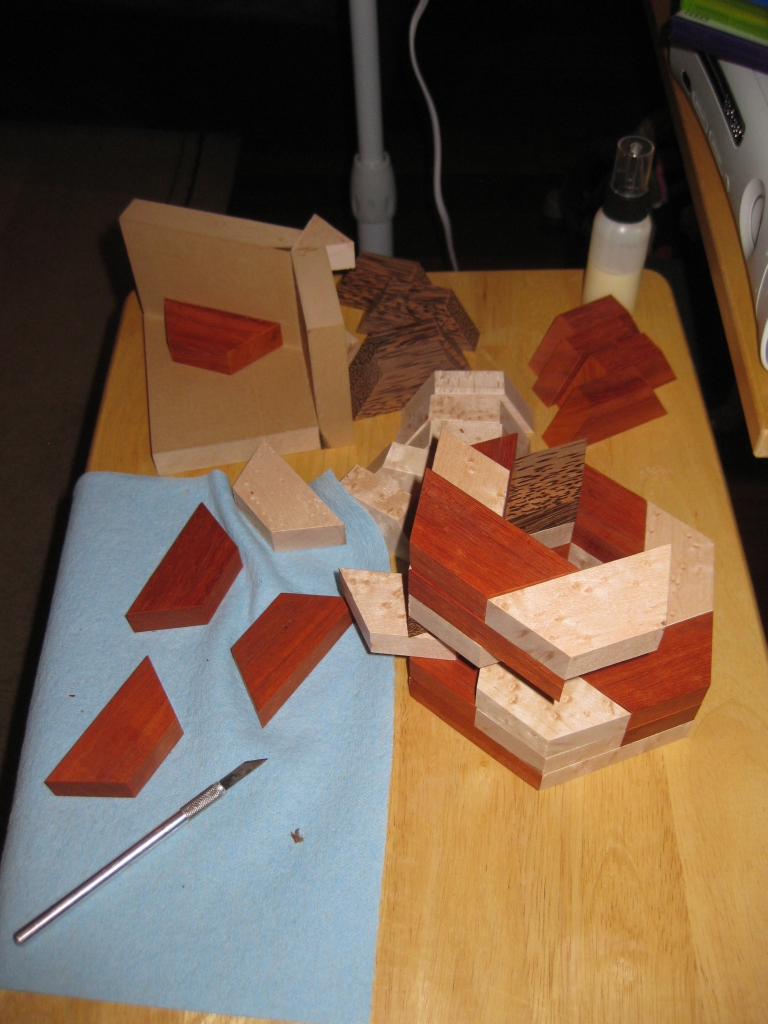
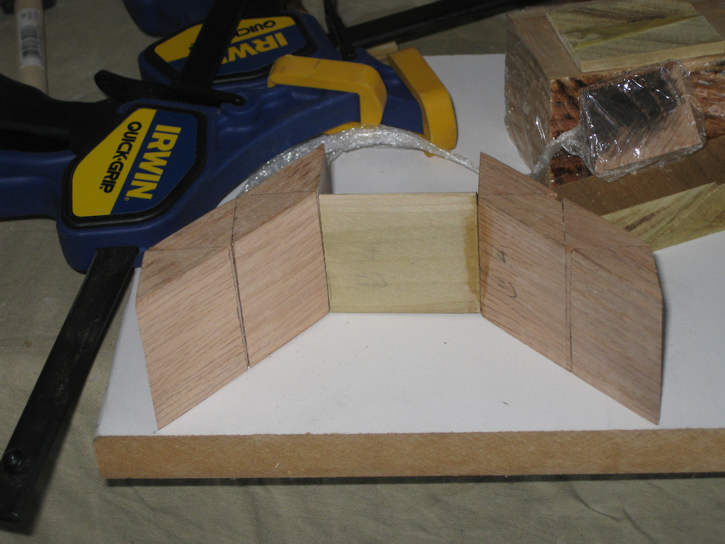
My first gluing jig was a pretty simple progression from my square corner gluing jig. Using the 60 degree crosscut sled I was able to create a simple base and walls at the correct angles, and re-inforced the centre angle with a couple of the equilateral triangles I’d cut when I was cutting the original pieces. The inner surface was waxed to prevent glue sticking to it (and hence sticking the pieces to the jig) while I was working. This worked pretty well, and I created the original puzzle using this jig, and the pieces I’d not glued in place to support and align the piece I was gluing.

Supporting the pieces while gluing

Supporting the pieces while gluing

Supporting the pieces while gluing

Supporting the pieces while gluing

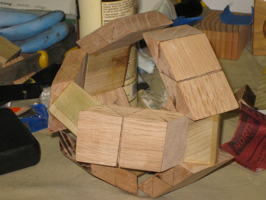
All said it worked fairly well, and the end result was reasonable. I did find that there were a couple of pieces which hadn’t lined up perfectly. But I used an interesting trick to fix that. With the six pieces of the puzzle together in the solution shape, I put the whole thing in the microwave for about a minute and a half on high. With my now warm puzzle, the glue is softened enough to allow the pieces to shift slightly if enough pressure is applied. By doing this I was able to re-align the couple of pieces I wasn’t happy with and get a near perfect fit. Now I’m not suggesting that this is a solve all for bad initial gluing as it really isn’t, bit in the few hundredths of an inch that I was misaligned on one or two pieces it can be corrected, rather than throwing away an entire piece.

Puzzles and Beer...

Puzzles and Beer…

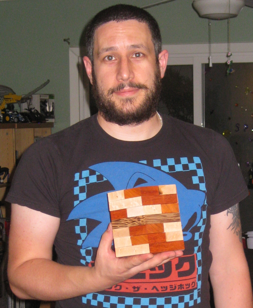
Me holding the puzzle

Me holding the puzzle

Scale next to a soda can

Scale next to a soda can


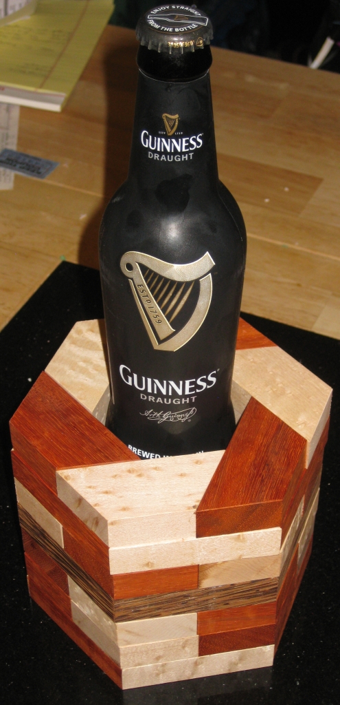
Overall I’m pretty happy with the results, although the size is certainly an issue. As you can see it’s a big puzzle, and not really realistic in terms of making them in a production run. It seems that I’m pretty good at forgetting how big a puzzle ends up when you glue all these ‘small’ pieces together. Part of the learning curve I’m on just now, but it’s all valuable information.

In part two I’ll look at making the puzzle in a more sensible size, and talk about the unique jig I built to help. Since I’ve had several requests, in part three I’ll talk a little about finishing.
From Square Sticks to Cubes

I recently wrote about the first of my puzzle making jigs to create square sticks as the first stage in creating the building blocks of many puzzles. With that jig successfully completed, and working pretty well, I had to move to the next stage and create some cubes. I said in the Square stick post that I’d tell you about it soon. Well, soon is now, and it’s time to make a crosscut sled!

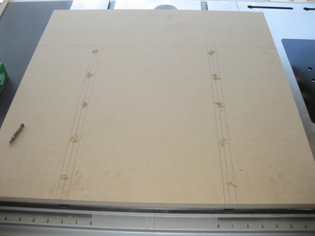
The starting point for a crosscut sled

The starting point for a crosscut sled

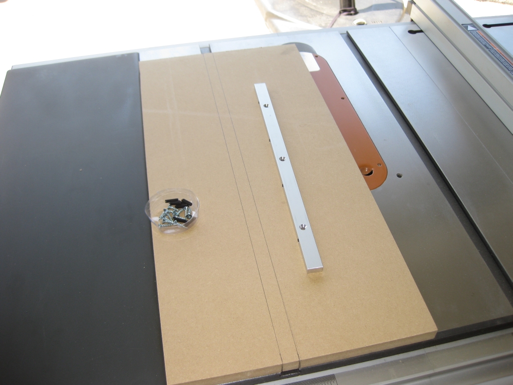
For this jig, I needed a larger platform than the square stick jig, and as such I was going to be using both miter slots on the table saw. I cut myself a slab of MDF and marked it up for adding runners. I don’t have enough of the fancy metal miter bar that I used for the last jig, so I made my own. Starting with a strip of wood rough cut to the correct size for my miter slot, I sneaked up on the correct width by taking thousands of an inch off at a time until I had a snug fit. It didn’t take as long as I thought it might, and I think I now have an even better runner than the metal versions I used on the first jig.

My intention was to drill and counter sink holes in the top of the sled and screw straight into the runners below. Sadly that didn’t quite work out as planned as I didn’t have screws which would fit. What I had was either too short or too long so I had to go to Plan B. I decided to screw through from the runner side into the base. As it turns out, it wasn’t too much of a change and in the end achieved the same end result.

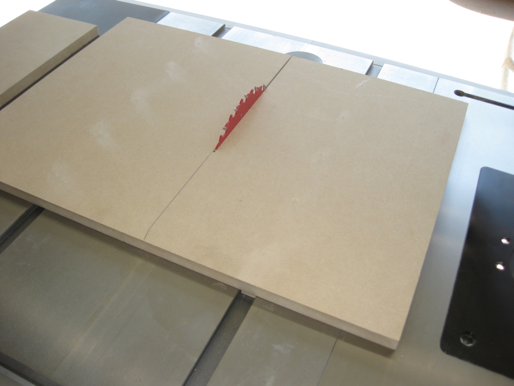
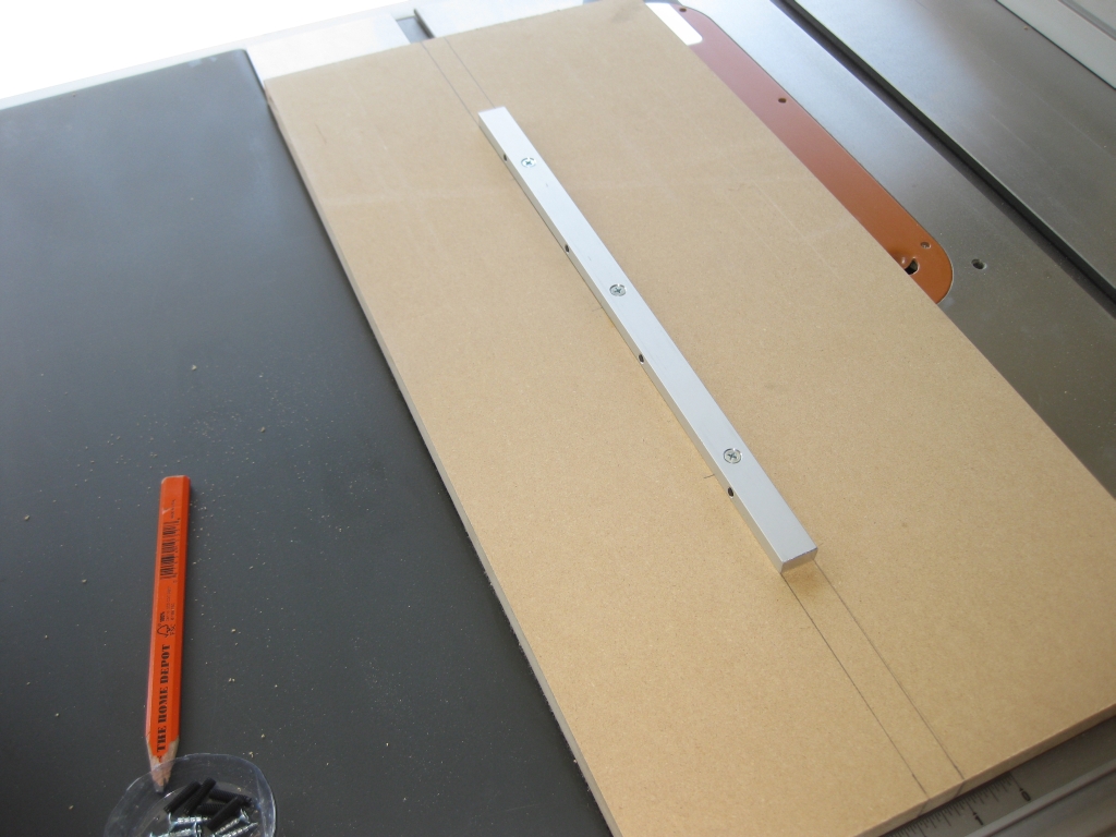
Runners mounted and a slot cut

Runners mounted and a slot cut

With the runners mounted, I flipped the jig over and tested the fit in the miter slots with the blade below the table. I had a couple of spots which were binding slightly, so I lightly sanded the offending areas until I had a tight but smooth fit with no wobble in the jig. For anyone wondering, the way I found out where the runners were binding was to run a sharpie along the length of the runner sides, then move the jig in the slots. When you take the jig back out, where the sharpie has been rubbed away is where you need to remove a small amount of material. Simple yet effective!

With the sled moving smoothly, I raised the blade up, and cut myself a slot part way through the sled. That slot will help aligning the crosscut fence as I need it to be perfectly square to the blade. Without having the blade through the sled that would be almost impossible.

Some reinforcement across the back of the sled.

Some reinforcement across the back of the sled.

Given the slot I’ve just created, I now have a potential weak point in the sled where it could flex, and degrade the cut. Despite how it may look in the photograph, I wasn’t trying to create a wing to add down-force to the sled.

Each of the three spacers on either side is screwed to the piece below with three screws, and gives enough clearance that with the blade raised to the point that the blade stiffeners are just below the base of the jig, it doesn’t cut into the cross bar. The cross bar keeps either side of the sled stable and prevents any twisting or warping of the sled. Yet again simple but effective. (I’m liking the fact that I can keep things simple. Less chance of things going wrong!)

A beautiful Dragonfly that stopped to see what I was doing

A beautiful Dragonfly that stopped to see what I was doing

Given that it was getting on for around 5 hours that I’d been working on the saw and building the jigs by this point, I took a break, stretched out my legs and back and relaxed for ten minutes. While I was doing that, I spotted a dragonfly floating around the garden. Standing watching him for a few minutes, he landed on the radio antenna for our car. Given that I still had the camera in my pocket from taking pictures of what I was doing, I grabbed it, as he posed for me! Looking at the pictures later, there really came out well, so I thought I’d share…

Anyway, back to the jig …

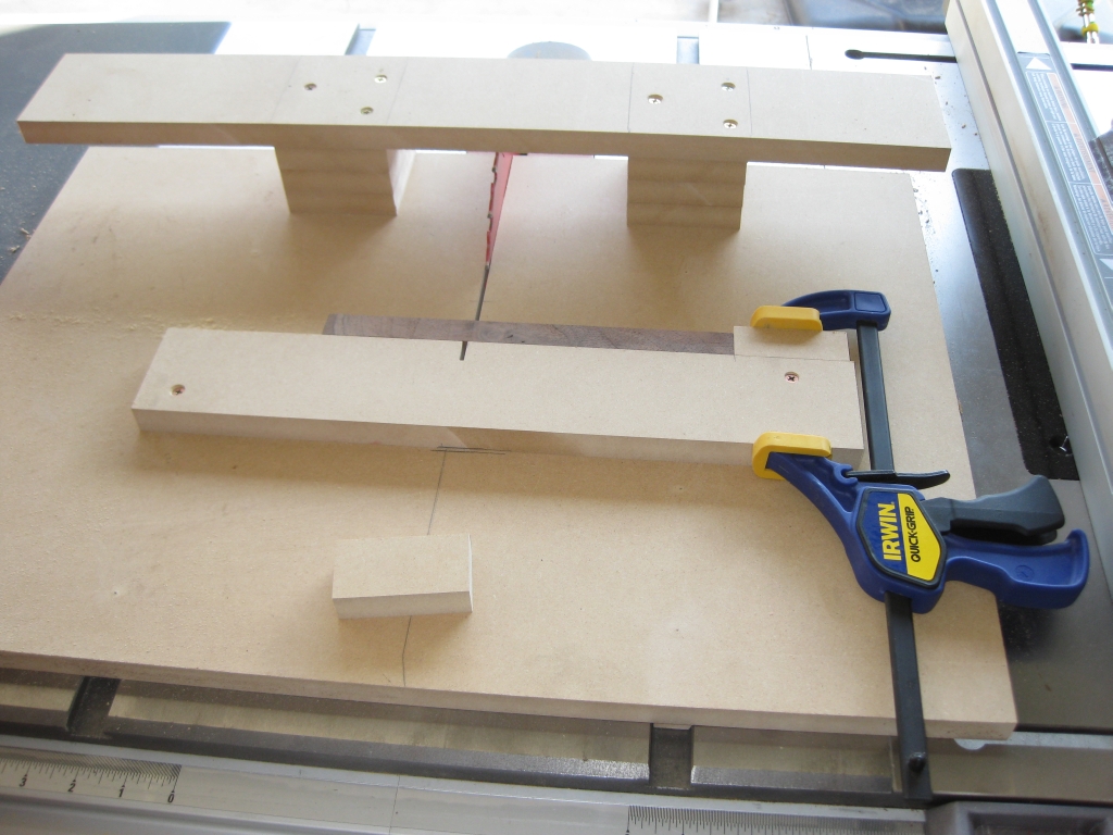
Adding the fence and a stop

Adding the fence and a stop

With the back reinforced, I had to add the fence to the sled. The important thing here is that it is at exactly 90 degrees to the saw blade. If it’s off, then the cut will not be square, which isn’t going to make for a good cube. Using the best square I have, I sat one edge against the blade, and the other against the fence board I’d cut. Keeping both edges in firm contact, I drilled one screw hole, counter sank and then screwed the fence to the sled at one corner. With one corner in place, I double and triple checked the fence was square, on both sides of the blade (using two squares). That may be a little overkill, since the blade shouldn’t be different on either side, but I figured it couldn’t hurt!

Everything checked, I pre-drilled and screwed the other side of the fence to the sled, and checked again for squareness. With everything looking good, it was time to add the stop. Now this was something that I’d been puzzling over for a good few days at this point, and hadn’t really figured out how I was going to perfectly measure the offset so that I ended up with good low tolerance cubes. As is ever the case, the answer came to me when I least expected it, in the shower in the morning before heading to work.

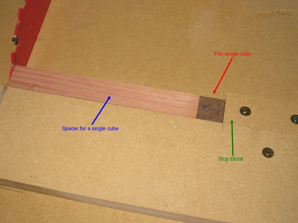
The answer. Make sure that the stop is far enough from the blade to make the biggest cut you’ll need, plus a bit. The reason … Well if you properly size a piece you want to cut (and I’ll get to that) then you can use that piece against the stop, then cut a ‘spacer’ by placing it against the fence, and the piece you want to cut, then cut that piece. You get a perfect spacer, and no complicated measuring required. (Other than the piece you want to end up with). Yes, I know that’s all very confusing, but I’ll annotate the pics below and it will make more sense!

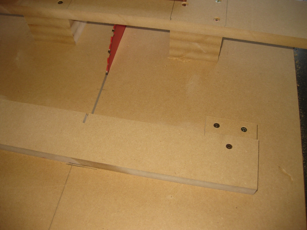
Clamp removed now that the stop is screwed in place

Clamp removed now that the stop is screwed in place

Having screwed the stop in place I could remove the clamp. The stop is placed 6″ from the blade. I’m unlikely to ever cut a stick that needs to be 6″, unless perhaps I’m making 18 piece burrs, so this is lots of space to create whatever sized stick I need.


Creating the spacer for a single cube

Creating the spacer for a single cube

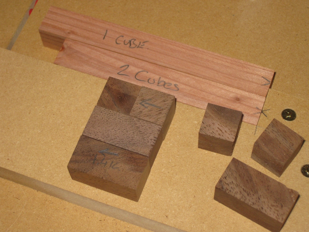
If you click on the image on the left, you’ll see I’ve annotated it to make my previous explanation simpler to understand. The single cube in walnut was created by shaving a few thousands at a time from the edge of the block and measuring after each pass until it matched the dimension of the square stick. In some regards, that is probably the most time consuming part of the process, as if you take off too much, then it’s a case of starting again.

With the first cube created by hand, it can be placed against the stop, then a long stick placed against it to create the spacer. In the diagram, you’ll see I created mine from some of the redwood sticks I’d cut when I was testing the square stick jig.

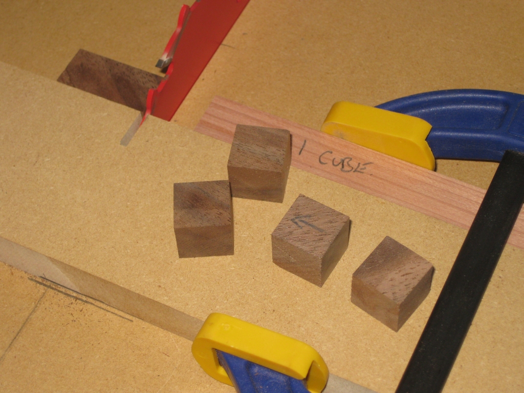
Batching out some cubes

Batching out some cubes

Now it’s a simple task of swapping the order of the pieces so that the spacer is against the stop, and batching out some cubes. I’ve used a clamp to keep the spacer in place, both against the fence, and hard up against the stop to make sure that it doesn’t move between cuts. It’s also important after each cut to clear out any dust that gets between the block and the fence as this will affect the accuracy of the cut. It is possible to adjust the spacer by adding feeler gauges between the stop and the spacer and before each run of cubes, I’ll need to check the sizes to make sure everything is within an acceptable tolerance.

Running through a few cubes, each cube came out almost perfectly. The worst cube had a tolerance of 0.001″ from the size of the square sticks. I can’t really complain when the cuts are that close. It’s going to be pretty good for any initial puzzles I make.

Making double size cubes

Making double size cubes

Now with a few cubes cut, I measured them, and selecting two that were exactly cubic, I placed them together and verified that the length was exactly double that of a single cube. Repeating the process I had used for the first cube, I cut a ‘two cube spacer’. This spacer will let me make double sized cubes, perfect for making any of Stewart Coffin’s Convolution/Involution/Involute puzzles.

Let the fun commence!

A Humbling Experience

Many of you know me on a few of the forums around and about the puzzling community, and a fairly well known Puzzle Box maker, let’s go with Allard’s name for him and call him ‘Stick guy’ posted asking what I was up to. It’s no secret I’ve bought a bunch of tools, and even started to use them to create the building blocks of puzzles, but I’ve never really mentioned what I was planning.

Well I answered Stick Guy’s “challenge”, and put up a brief summary of what I had been doing and what I was doing. You’ll know if you’re a regular reader that I designed a puzzle which I call Lock Cube some time back. I even prototyped it in Lego, then had it printed at Shapeways. Well at some point I’ll be making it out of wood too. (At least that’s the plan)

So here’s where things get interesting, and when I get to the point of the title of the post. Seems like a few people out there are interested in owning a copy of my Lock Cube, when I make it.

Now at this point, many things go through my head, including a few that I can’t print…

“Are you serious?”
“You really want one?”
“People want to own a puzzle I designed?”
“Is my puzzle good enough?”
“What will people think of it?”

The bottom line is that I was truly humbled by the response from quite a few people asking if I’d make a copy for them. I never expected to make more than just the one for myself, so this was a shock for me, and really left me not quite sure what to say. Quite impressive really since I’ve written an entire post about it!

So to everyone that has already shouted ‘Me please’ for a copy of a puzzle that I’ve not yet made from wood – Thank you.

If you want a copy, let me know. I’m not promising anything at this point, but I’ll keep it in mind as I make those early copies.

Cutting Square Sticks

The start to many a good puzzle is a square stick. But not just any square stick. One which is accurately sized along its length and each side square to its neighbor. Not an easy task.

A while back, Scott Peterson sent me a tutorial for building a table saw jig to create square sticks. Over the Labor Day weekend which is a holiday for us in the US, I set about making the jig (mostly) following Scott’s tutorial so that I’m firmly on the road to making my own puzzles. Scott kindly game me permission to make the tutorial available to anyone that wants it, so feel free to download a copy.

The following is my attempt at creating square sticks …

Starting off with a sheet of 3/4″ MDF I cut myself a strip that was wide enough to go between the miter slot and just past the blade of the saw. I left a good sized area on the other side of the miter slot so I had room to attach a handle to help push the jig through the cut, and back after the cut. I marked the position for the miter bar and after pre-drilling the holes, screwed it in place.

Preparing to attach the miter bar.

Preparing to attach the miter bar.

Miter bar attached to the base of the jig

Miter bar attached to the base of the jig

The miter bar that I bought has plastic screws that protrude from one side to ensure that the bar is a perfect for for the slot. Taking some time I adjusted each of the screws to make sure that there was no wobble in the slot, as this would compromise the cut.

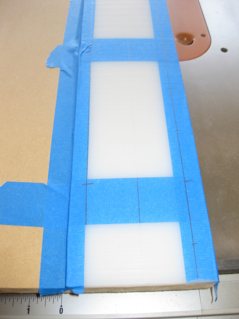
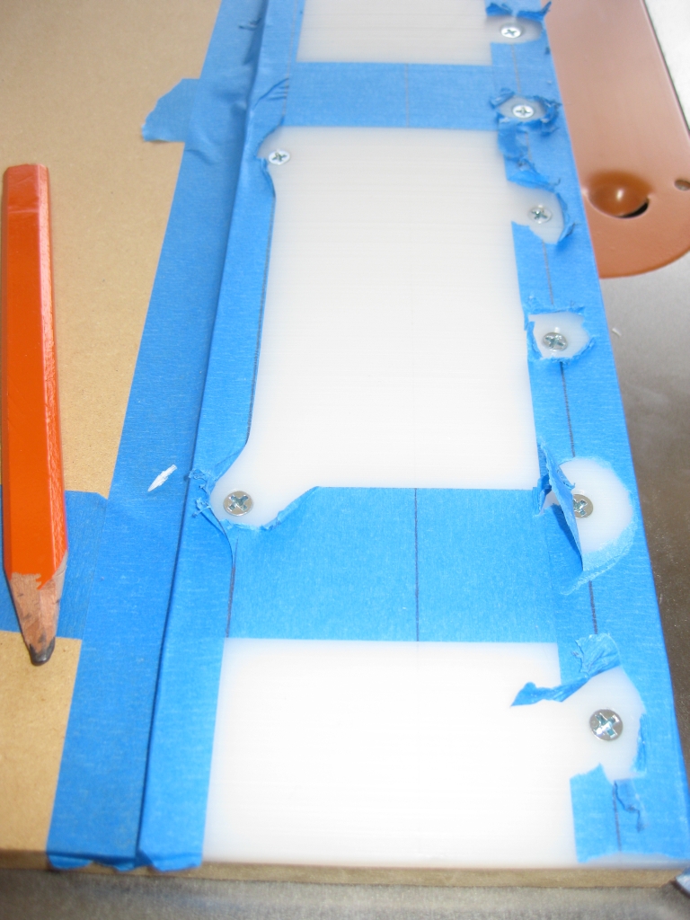
Taking Scott’s advice, I also added a UHMW plastic base to the cut side of the jig to back up the cut and help prevent tearout. Using blue tape I secured the plastic to the base, and marked out the positions for the screws, predrilled, countersunk then screwed the plate down. The Blue tape came in really handy as it’s almost impossible to mark the UHMW plastic with a pencil.

UHMW plastic set in place ready for drilling and screwing

UHMW plastic set in place ready for drilling and screwing

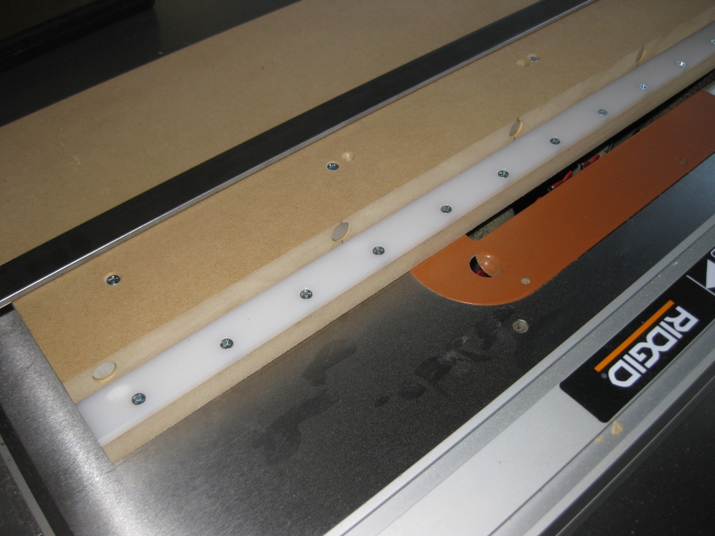
The UHMW screwed down.  Note the screws are all below the surface of the plastic

The UHMW screwed down. Note the screws are all below the surface of the plastic

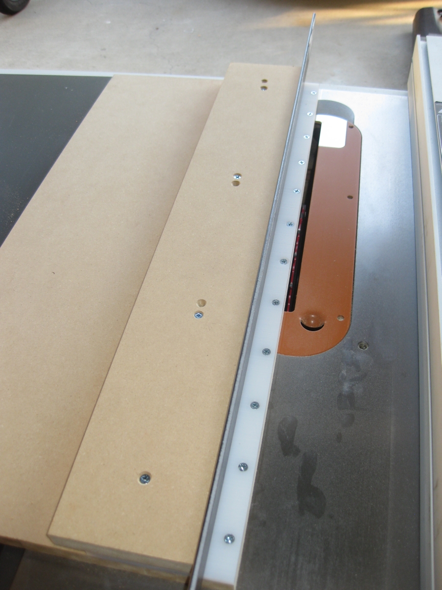
With that done, It was time to make the first cut, and trim the extra material that I had left off the edge of the jig, ensuring that the blade ran along the edge of the jig which is needed for an accurate cut. Making sure that the blade was at 90 degrees to the table top, I made the first cut. And immediately noticed that there was a gap at the front of the jig which wasn’t there at the back. It was pretty small, but enough that I could see light between the blade and the jig, so I knew the jig wasn’t good enough. It seems that I didn’t do a good enough job of adjusting the miter bar, so I readjusted, and remade the cut. Fortunately, I’d left enough space between the edge of the jig and the screws holding the UHMW plastic down to be able to do this. This time things were much better and I got the accurate cut I was looking for.

Ready to screw the fence to the jig

Ready to screw the fence to the jig

The magnets to hold the steel bar in place

The magnets to hold the steel bar in place

Fence screwed gown and ready to go.

Fence screwed gown and ready to go.

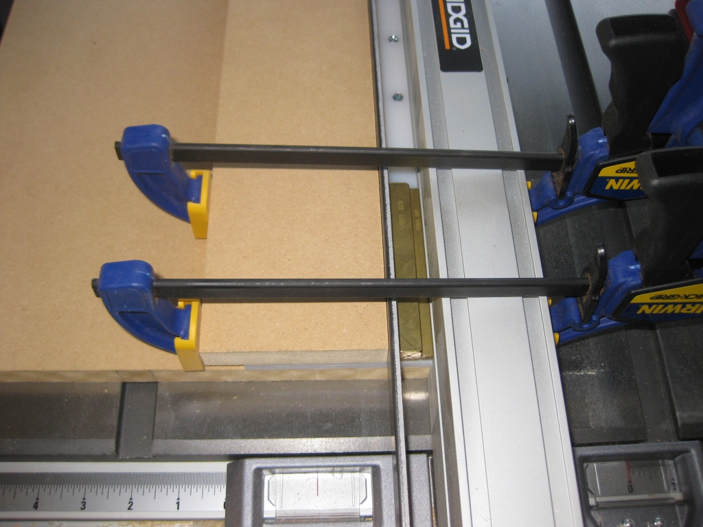
Next up I need to install the fence on the sled which the stick will be clamped against when making the square sticks. As Scott notes in the tutorial, I have a steel bar as a spacer, and use some brass feeler gauges to get an accurate cut. I also embedded some Neodymium magnets in the fence to hold the steel spacer firmly against the fence. The fence is clamped securely against the saw’s rip fence, then predrilled and screwed down.

Those eagle eyed readers out there may notice a couple of extra drilled holes in the fence. Well yet again, I managed to get things a bit wrong, and screwed the fence in a little squint. Now that’s not a lot of use when you’re trying to get accurate cuts, so I re-drilled and re-attached the fence. So there’s a couple of extra holes there now. It won’t affect the jig, but a squint fence would have!


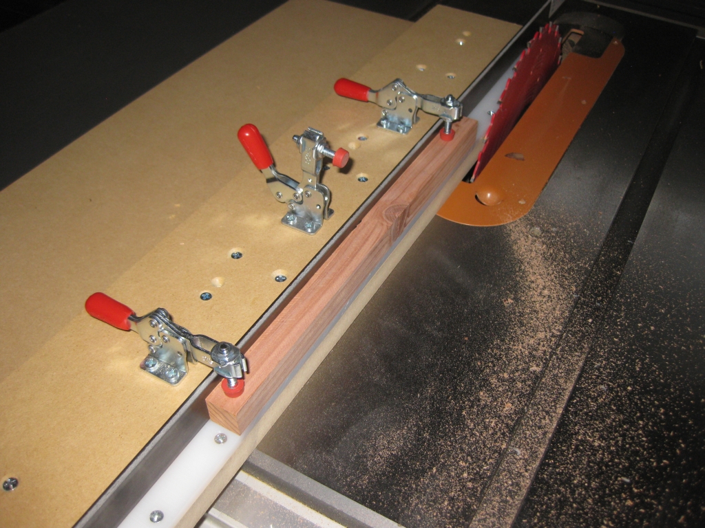
Adding some toggle clamps to the fence and I have something where my fingers are well out of the way, and the sticks will be firmly held against the fence.

Cutting a stick square

Cutting a stick square

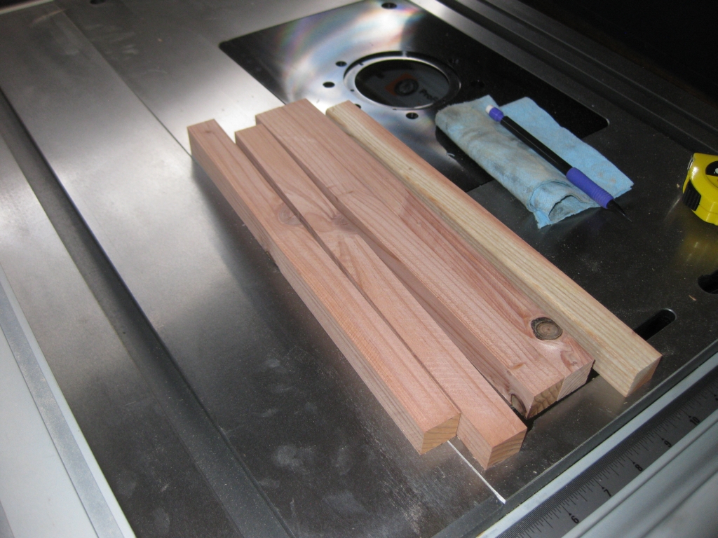
Ten minutes later; five identical sticks

Ten minutes later; five identical sticks

With everything set, It was time to put some sticks in there and see if I could make some square sticks and whether they would be accurate or not. At this point I was looking to test the jig, so I used some redwood I had to spare, and ripped it into roughly sized sticks. Now you’ll notice the knots in the wood so even I knew things weren’t going to be perfect. Still it was good enough for a test.

Measuring the sticks using my digital calipers, I am getting sticks with a 0.005″ tolerance between either end of the 12″ sticks. That’s not too shabby. Given the knots in the wood, which will most likely make it twist as the knot is cut, I’m fairly happy with the results. At this stage in my puzzle making career, it should be more than accurate enough for making cube based puzzles, and burrs.

But that’s not the end of the story ….

I came back to the jig in the morning, used some walnut that I had bought a few weeks back for making puzzles, and used that to get some square sticks. The walnut is much nicer wood, no knots, and a beautiful grain to it …. The results. I cut four 9″ long sticks with a tolerence of 0.002″ across all four sticks. Now that’s a result I’m proud of!

Next up, I need to create a crosscut sled so that I can cut these sticks into accurate cubes for use in making puzzles. That post is coming soon, so stay tuned.

Building a Matrioshka (Part 3)

This entry is part 3 of 3 in the series Building a MaTRIOshka

At the end of the last post, I’d finished making all the individual parts that would make up the puzzle, and was ready to start putting things together. The number of individual parts has reduced from the original 54 to just 18, but things are no less daunting at this stage.

All 18 pieces ready for final glueup

All 18 pieces ready for final glueup

The biggest problem remaining was how on earth I was going to glue the ends to the bridge. There are no square ends on this thing that you can put a clamp on, so it makes holding the pieces together a real challenge. Building a gluing jig was probably the right way to go, but even that made for some interesting clamping!

Gluing Jig

Gluing Jig

I decided not to try to make a jig that would glue both ends at the same time. I wanted something simple that would support the pieces as I glued them, and in the end, the jig was much simpler than I thought it needed to be. Some of the original scrap pieces I had left served fairly well, and also meant that I could glue both sides at the same time. I’m not an expert woodworker, I don’t have a lot of ‘spare’ or scrap wood lying about (remember I’m only starting out doing this, so no reserve of wood to pick from) so this did the job.

Gluing Jig, yes it's ugly!

Gluing Jig, yes it's ugly!

Sticking with the very simple jig above, I could glue one end at a time and create the pieces. Granted if I were doing this in bulk, or attempting to create something I could sell, I’d be thinking about a more efficient scheme. For now, this works, and is all I needed.

One down, 5 to go!

The first finished piece

The first finished piece

After several hours over the weekend (since I do all this in my spare time, which I don’t have a lot of just now!) I had 6 pieces glued up and ready for a test fit. Yes, the time had come to see how much of a mess I’d made of my first ever serious attempt at making a puzzle!

The six finished pieces

The six finished pieces

With some hesitancy, I took the plunge and tried to fit the pieces together into the final puzzle … It’s a tight fit, but things were taking shape! I spent a little time with the sandpaper and sanded the pieces down just a hair. Using my digital calipers, the bridge was 1.333″, and the edges were around 1.49″. So there really wasn’t a lot in it, but enough that some work was required. A little bit of sanding on each of the pieces, and I had them down to around 1.32″.

Test fit

Test fit

And here the story ends unfortunately. When I tried to put all six pieces together, tiny inaccuracies in the fit of the pieces, and minute misalignment between the ends meant that the whole puzzle is just enough off that it’s not going to go together and slide the way it is supposed to. Despite the end result, I don’t consider this a failure. You may remember back in the first post, I said that this was a learning experience for me. And I’ve learned a lot through the process. I’m sure I’ll come back to this puzzle in the future, and expect version two to be better!